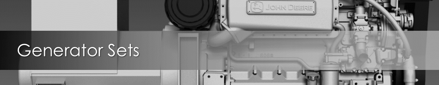

The RER (Remote Extended Run) generator set is designed to provide reliable operation in remote locations and to extend regular service intervals to up to 4 months (3000 hours) without any sacrifice in performance or overall equipment life.
Unique Features:
- Long Run Oil System™
- Oversize fuel tank.
- Specially-designed cooling system.
- Enclosure designed to allow sufficient air to flow to the unit even if one side should become blocked.
- Monitored and controlled remotely on a computer or a iOS/Android smartphone app.
- Paralleling of multiple smaller gensets rather than a single larger genset to save fuel when load demand is low.
Feature Details
Long Run Oil System™
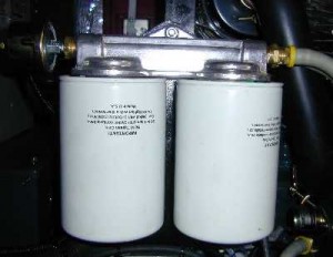
- The oil reservoir capacity has been enlarged to allow the engine to operate for a period of 3,000 hours (4 months). Consideration has been given to the normal oil consumption of the engine under any load conditions, as well as to the maximum oil consumption expected as the engine wears.
- An oil suction strainer extends into the reservoir to a sufficient depth to ensure that the engine will to continue to have adequate lubrication throughout the extended service interval.
- Baffles, located in the oil reservoir, provide the engine with warmed oil in cold operating conditions.
- A heat exchanger has been added to normalise the oil temperature with the coolant bypass circuit. In high ambient operating conditions, the heat exchanger will cool the oil, while in low ambient temperatures, the heat exchanger will warm the oil even when the thermostat is closed.
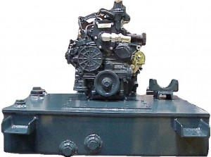
- Two large capacity, full flow, lube oil filters are easily accessed for servicing. The filter assembly is equipped with individual relief valves on each filter. If one filter becomes plugged, the other remains operational.
- An internal oil pressure relief valve regulates engine oil pressure.
Cooling System
The cooling system consists the following components, which are matched to provide the engine with proper cooling even under conditions of severe heat or cold:
- Two electrically operated fans.
- A thermostat for engine coolant
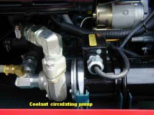
- An electrically-driven coolant circulation pump
- Various components to signal and monitor the cooling system.
The flow circuit consists of:
- A circulating pump that draws coolant (50/50 water and low silicate antifreeze) from the radiator and discharges the coolant through the engine’s cooling passages.
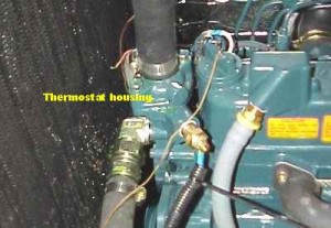
- A thermostat in the return to the radiator that regulates the engine’s temperature.
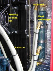
- A bypass circuit that redirects some coolant through a heat exchanger to warm or cool the engine oil.
When the engine reaches its normal operating temperature, the thermostat allows most of the coolant flow to return to the radiator where waste heat is exchanged to the atmosphere by one or both of the electric fans, as required.
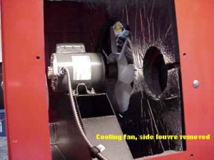
The primary fan, located in the engine enclosure, is powered by the same 115 VAC supply circuit as the circulating pump. This low flow fan maintains the engine’s temperature even in extremely cold operating conditions. A high flow secondary fan is thermostatically controlled. It cycles on or off as dictated by ambient temperature and engine load conditions. The large volume cooling system allows for degradation caused by foreign materials (within the system or on radiant surfaces).
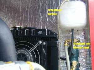
Other cooling system items include an overflow bottle for the radiator’s coolant. The secondary fan motor, located in the plenum chamber, is cooled by the fan’s air flow.
Fuel System
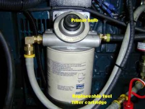
A single fuel filter is located “upstream” from the mechanical fuel transfer pump. There is a priming bulb located on the filter head. The main tank on the base frame is angled slightly to allow water to drain away from the engine’s suction and return fittings, which are located near the bottom of the fuel tank.
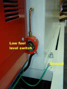
The fuel tank is a single wall reservoir with approximately 500 US gallons of capacity. A 2 inch NPT filler neck is surrounded by a splash guard. One fuel level sender is provided to pre-alarm low fuel level. Locks are provided to protect the contents.
Air Intake System
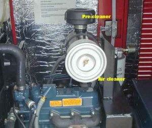
A pre-filter, designed to remove 95 percent of moderate to heavy dust, is located on the air filter inlet.
AC DC
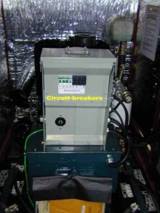
The generator is brushless and has a solid state automatic voltage regulator. A main circuit breaker protects the generator from electrical faults and branch circuit breakers are provided on all circuits. All components of the electrical system are bonded and a grounding lug is supplied.
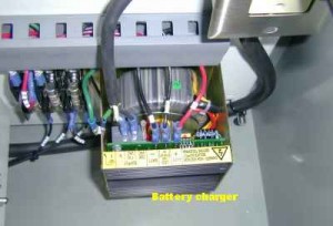
There are two, paralleled, 12 volt lead acid batteries for the starting circuit. An automatic, 3 amp, battery charger, located in the rear control panel, maintains both batteries. When the set is running there is very little DC load.
Enclosure
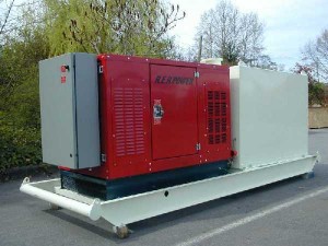
The enclosure is designed to allow sufficient air to flow to the unit even if one side should become blocked by snow, ice, leaves and so on. The panels at the radiator end are removable for servicing the main cooling fan and motor. The enclosure is also rodent proof. The powder coated outer and inner surfaces protect the metal from deterioration.
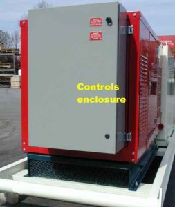
Control and Metering
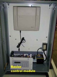
A control module is installed which provides engine and generator monitoring functions. As, well the control module supplies signals to various engine subsystem tasks. For details, the specific manual is provided. Wiring details are shown on the wiring schematics.
A reset feature can be used to count down hours to the engine’s service intervals. As well, the control module stores accumulated kilowatt hours and total running time.
If an alarm or critical fault occur, fault monitoring, with adjustable parameters, allows the control module to alert a designated operator, via wireless modem, satellite or microwave communication.
Shutdowns and Alarms
Situations that would result in an engine failure, such as low oil level/pressure, engine over/under-speed, are monitored and, at a predetermined point, will result in the shutdown of the generator set.
In addition to the shutdown points, there are predetermined alarm conditions. At the alarm point, a signal can be generated to notify the operators of potentially dangerous conditions. The alarm conditions include:
- Low fuel level
- Over-cranking of the starting motor.
- Sender failure (oil pressure, coolant temperature).
- High or low speed signal.
- Low battery voltage.
- Battery over-voltage.
- Generator overload.
- Scheduled maintenance due.